

Mobile DVR Installation: A Fleet Wiring and Test Checklist
A reliable mobile DVR installation needs a verified power plan, compatible cameras, protected cabling and a recorded acceptance test. Seeing live video on the first power-up is only one part of commissioning. The fleet also needs to know that recording, shutdown and video retrieval behave as intended.
This checklist helps fleet buyers and integrators prepare an installation specification for trucks, buses and other commercial vehicles. Use the selected recorder's manual and the vehicle manufacturer's instructions for the actual wiring work.
Prepare the installation pack before fitting hardware
Create a pack for each materially different vehicle configuration. Include the vehicle type, recorder model, camera locations, channel names, monitor arrangement and installation drawings.
Record these requirements before the installer starts:
- Vehicle electrical supply and approved connection points.
- Recorder and camera input requirements.
- Required recording periods and shutdown behavior.
- Camera signal formats, connectors and cable lengths.
- Storage configuration and retention objective.
- Supported network, positioning and platform functions.
- Access for maintenance and replacement.
Use a labeled channel plan such as front road, driver area, left side and rear. The names should remain consistent in the recorder, platform and handover sheet.
For decisions about the overall architecture, refer to Commercial Vehicle Camera Systems. This installation checklist starts after that architecture has been chosen.
Confirm power and ignition behavior for the exact model
An installation may involve a permanent supply, an ignition-related input and a ground connection. Their function, permitted voltage and connection method depend on the recorder and vehicle.
For example, the manufacturer-specific skEYEwatch installation guide documents constant power, keyed power and ground for its system. Those instructions demonstrate why a model-specific diagram matters; its wire colors and fuse values should not be copied into another manufacturer's installation.
Have a qualified installer verify the proposed connections and electrical protection. Confirm whether the selected unit supports delayed shutdown or other post-ignition behavior, and document the intended setting.
Test the recorder through normal start, operation, ignition-off and restart sequences. Observe whether it shuts down cleanly and resumes the intended recording configuration. If parked recording is required, assess its power demand and battery-protection arrangement as part of the project.
Place the recorder where it can be serviced
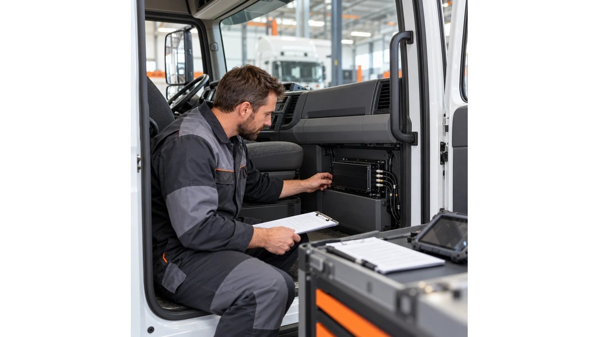
Choose a mounting location that meets the equipment's documented limits and leaves space for connectors, ventilation and maintenance access.
Avoid a location chosen only because the recorder fits physically. Consider water exposure, heat, vibration, passenger access and interference with vehicle equipment. Secure the unit with the approved mounting method.
The technician should be able to identify the unit, inspect connections and reach serviceable components without dismantling unrelated vehicle systems. Record the location with a photograph for the fleet's maintenance file.
Verify cameras and cables as a complete chain
Confirm the camera output, recorder input and monitor compatibility together. A connector that fits mechanically does not prove matching pin assignments, power requirements or video format.
For mixed AHD and IP projects, use the AHD vs IP compatibility guide to organize the questions, then verify the selected hardware combination with its documentation.
Label both ends of every cable. Route and secure the harness according to the vehicle and equipment instructions, accounting for moving parts, sharp edges and maintenance access. Use approved sealing and strain relief where cables pass between environments.
Check the final view after the camera is mounted. Confirm that the intended area remains visible with representative loads, doors and accessories in their working positions.
Configure recording separately from remote viewing
Document the settings that control recorded evidence: active channels, resolution, frame rate, encoding, overwrite behavior and any supported event settings.
Do not assume that a clear low-bandwidth remote view represents the quality stored on the recorder. Test both paths where the system supports separate recording and transmission settings.
Size storage against the actual recording configuration. AlwayCare's Fleet MDVR Storage Calculator explains the planning calculation. The installation test should also confirm that the intended media is recognized and that recorded files can be retrieved.
If remote access is part of the project, verify the selected unit's supported carrier configuration, server settings, credentials and permissions. Test local recording without relying on a continuous mobile connection; confirm the documented behavior of that model rather than assuming all recorders work identically.
Run a recorded acceptance test
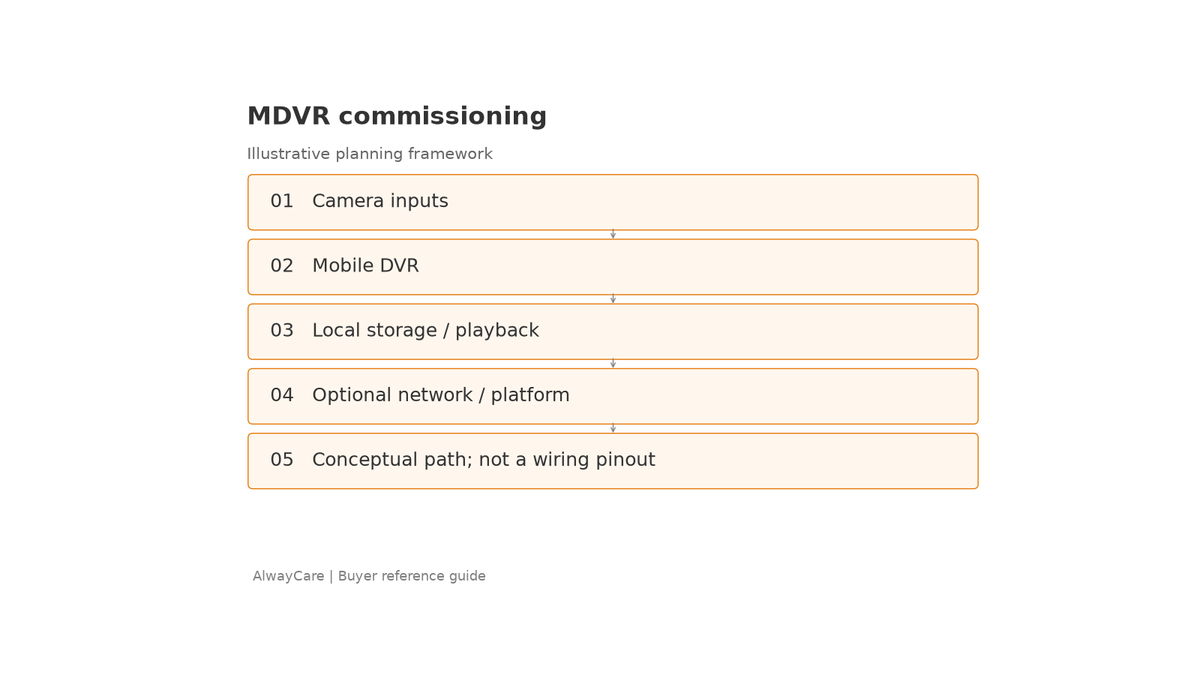
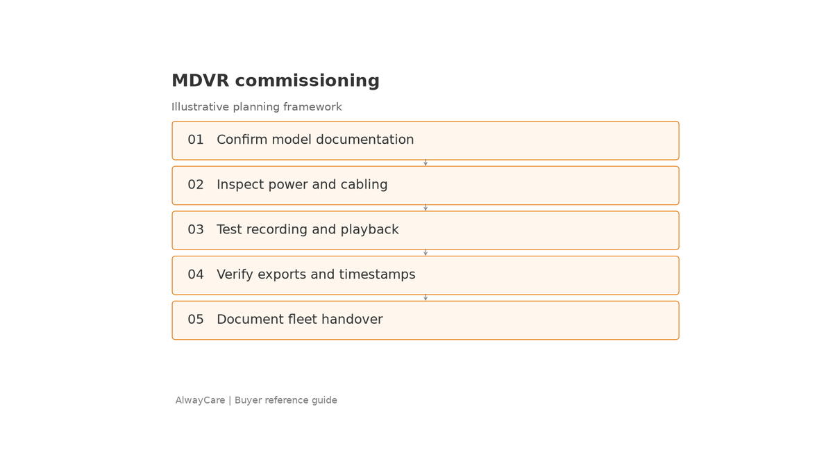
Create a short recording with identifiable events and a noted reference time. Check the same period through local playback and the intended export or platform workflow.
| Test | What the handover record should show |
|---|---|
| Start and restart | Unit starts and returns to the required configuration |
| Channel mapping | Camera views match their labels |
| Live image | Required areas are visible in the relevant conditions |
| Recording | Files exist for every channel and period in scope |
| Time | Timestamp and time-zone settings match the project plan |
| Playback and export | Authorized staff can retrieve and open a sample |
| Ignition-off behavior | Recording and shutdown follow the agreed settings |
| Network interruption | Actual behavior matches the model's documented capability |
| Monitor or trigger function | Supported functions respond as specified |
Mark each item as passed, failed or outside scope. Keep failed items open until correction and retest. A platform showing the vehicle as online should not close an unresolved recording fault.
Prepare a handover that another technician can use
The handover pack should contain the wiring diagram, connection records, hardware identifiers, software version, configuration file where supported, test results and installation photographs.
For international rollouts, verify electrical compatibility and local installation responsibility for each fleet. Cellular module and carrier suitability should be checked per operating country. A vehicle configuration commissioned in one market should not be copied automatically to another.
Include named owners for account access, configuration changes and maintenance. Record where model-specific manuals are stored and how replacement equipment will be commissioned.
Request a configuration review with clear inputs
Review AlwayCare's Mobile DVR range against the camera, recording and vehicle requirements. Confirm all specifications for the exact model and version proposed.
For a useful project review, send AlwayCare the vehicle types, camera layout and operating countries, together with the recording objective, power plan and acceptance checklist.
Frequently asked questions
Can the same wiring diagram be used for every MDVR?
No. Verify the recorder, harness and vehicle documentation. Similar-looking connectors or wire colors are not sufficient evidence of compatibility.
Is a live image enough to accept the installation?
No. Confirm recording, playback, export, timestamps and the agreed power-cycle behavior as well.
Should every vehicle in a fleet be tested?
Each installed system needs a handover check. A representative pilot helps define the configuration, but it does not prove that every later installation was completed correctly.